
We design the mechanics of your device and stay with the design through tooling, first parts and manufacture.
Mechanical engineering for medical devices covers the physical structure of the product: the enclosure, the moving parts, the sealing interfaces, and the features that hold components in position through handling, cleaning and use. The work begins with the architecture and ends with drawings a supplier can quote and manufacture from.
Between those points sits the mechanical design itself. Materials are selected against the loads, chemicals and contact conditions the device meets. Processes are chosen for the volumes involved. Dimensions are toleranced so that the assembly functions across the range those processes produce rather than at nominal alone. Each decision constrains the other two, and a change to any one of them reopens the rest.
Perdigó Medical carries out this work under an ISO 13485 quality management system certified by SGS, so the rationale always forms part of the deliverable alongside the geometry.
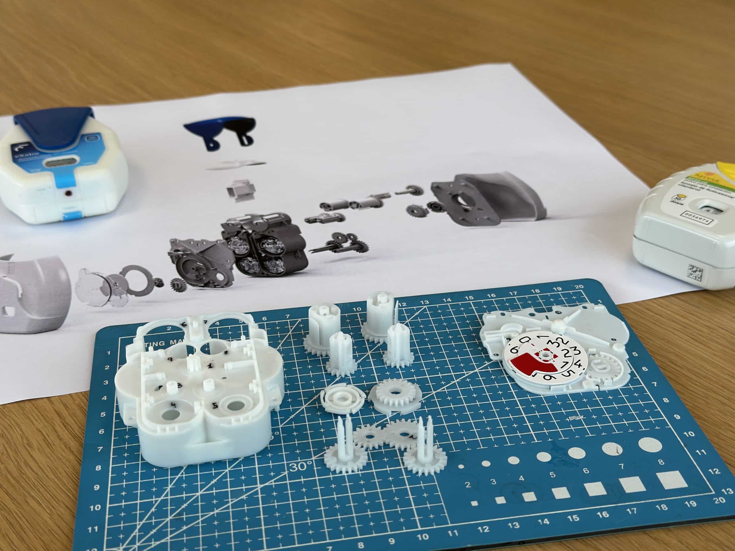
The mechanical engineers at Perdigó generate and assess mechanical concepts, define the architecture, and establish the parts, interfaces and mechanisms that deliver the device function. The selected concept is developed into a feasible system layout, with load paths, movements and internal volumes resolved to the point where they can be evaluated.
Analytical models support concept selection. Forces, motion, spring rates, envelopes and flow are calculated to compare options before geometry is committed, and proof-of-concept parts are printed in-house so that mechanisms can be assessed physically.
Concept work is performed in SolidWorks and Autodesk Fusion, and the output is a system layout your development plan can be built around.
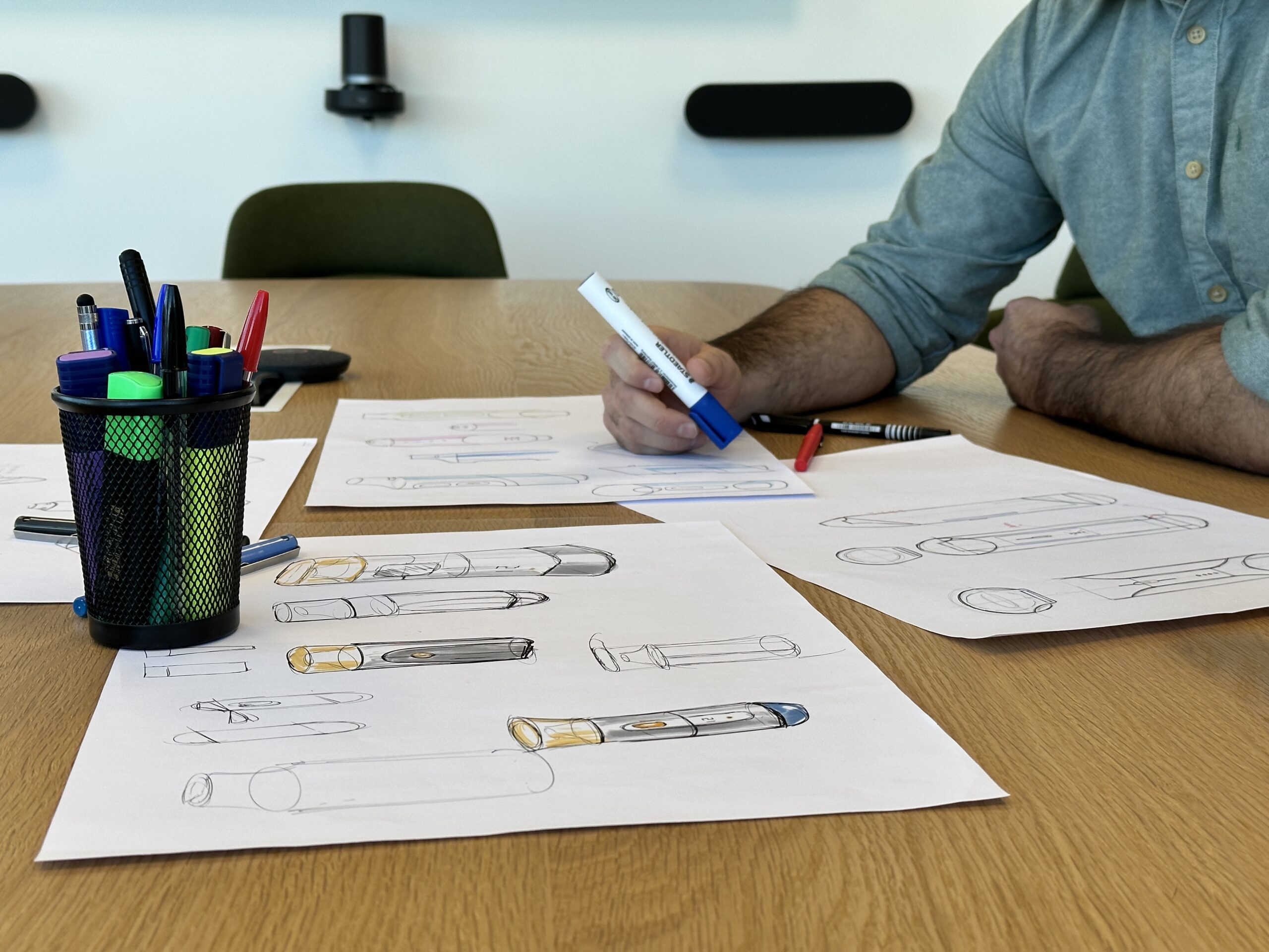
Detailed design develops the selected concept into a released design. It is the largest phase of the mechanical work and runs as a set of parallel activities, each informing the others as parts, tolerances and processes converge. The activities within it are the following:
Detailed design closes when the drawings, the tolerances and the selected processes are consistent with each other.
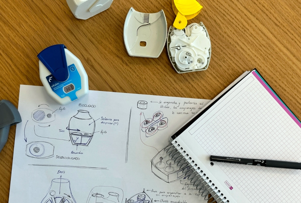
We apply design for manufacturing and design for manufacturing and assembly across machined, printed, moulded and assembled parts. That means simplifying geometry, reducing part count, rationalising assembly sequences and adapting tolerances to what the selected process holds.
Where a standard defines that capability, the tolerance scheme follows it. Moulded parts are set against DIN 16742 and general dimensions against ISO 2768-1, with individual tolerancing wherever function demands tighter control.
Process capability also changes with volume. A machined or printed prototype part and its moulded production equivalent hold different tolerances and fail by different mechanisms.
Geometry carried through development is therefore reviewed against the production process before release. Their quotations, toolmaker comments and first-part measurements feed back into the model while the design can still absorb them.
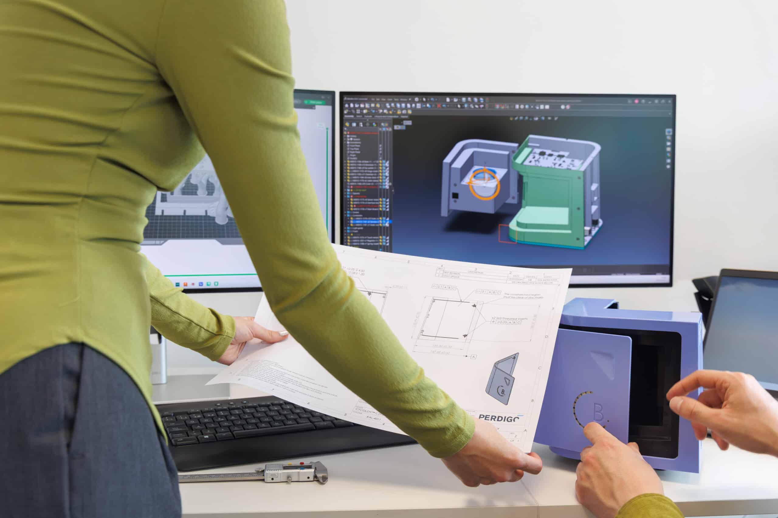
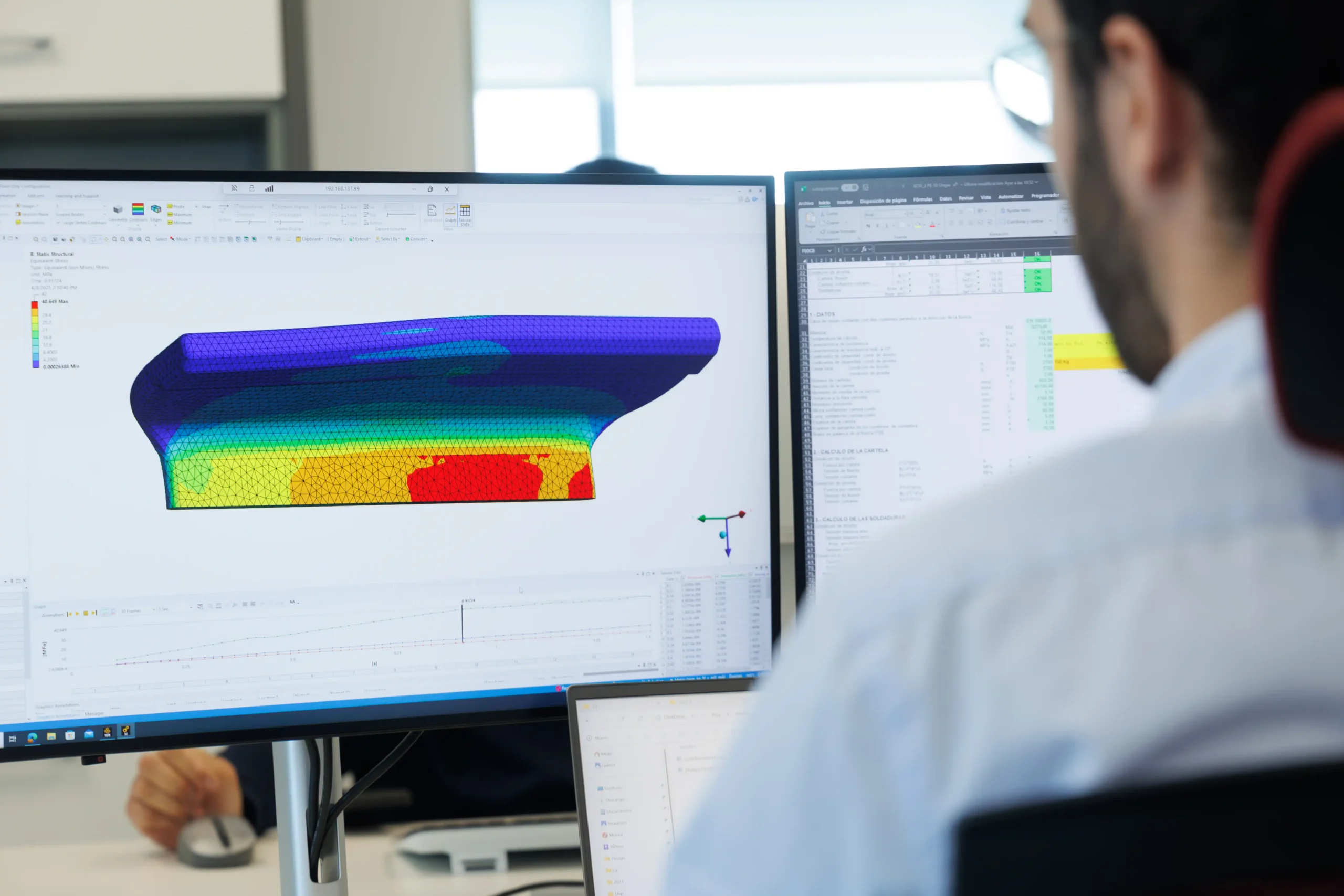
Decisions that depend on load, motion or deflection are settled by calculation before hardware is committed. We perform structural calculations and finite element analysis of parts and assemblies, using SolidWorks Simulation and ANSYS.
These cover stresses, deformation, contact behaviour and comparison between design options. Mechanism motion and load analysis runs alongside them, establishing the forces a mechanism generates so that the parts carrying those forces are sized against a figure.
Both are simplified representations of the physical part. Their limits are treated as part of the result. Where a design decision rests on an analysis, the model is validated against prototype or test data before that decision is taken.
Analysis narrows the options and prototypes settle what remains. We design prototype parts and prepare the manufacturing files, then print selected parts in house on SLA and FDM machines. Engineering builds are assembled, disassembled and reworked as the design develops. Build issues and configuration are documented as they arise, so each change traces back to the version that prompted it.
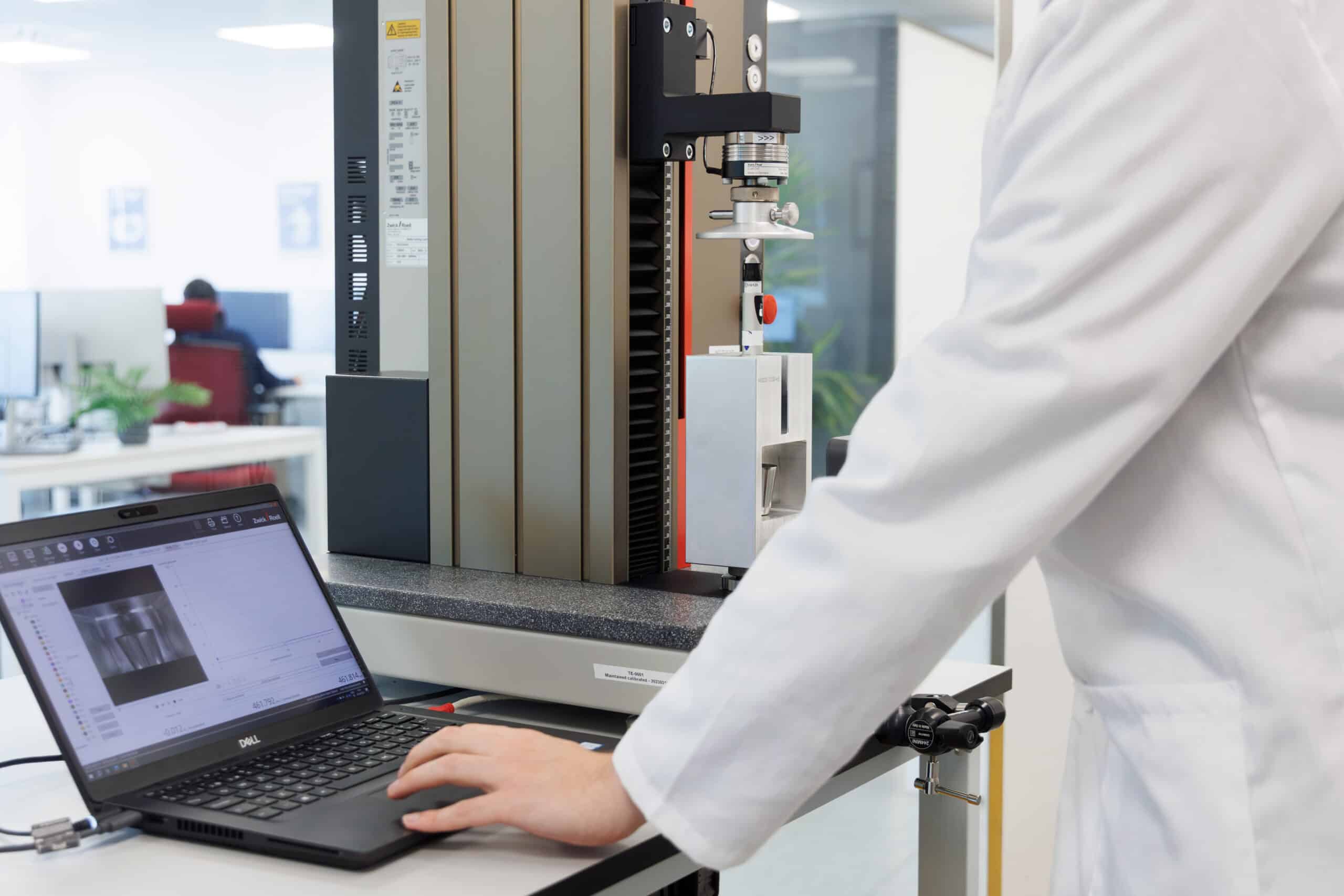
Testing those builds requires hardware of its own. Mechanical fixtures are designed and commissioned for development and verification testing, covering sample location, loading, interfaces and repeatable setup. Parts returning from those tests are inspected against the drawings, as are parts received from suppliers, with conformity or deviation recorded. Where a part has failed, teardown and inspection establish the evidence and the correction is taken in the design.
We prepare the mechanical design outputs for that handover, support supplier quotation and selection, and close DFM comments. Involvement continues through first builds and inspections under ISO 13485 design transfer and supplier controls.
Tooling is coordinated on the same basis. We specify the tooling requirements, issue the design data and attend toolmaker reviews and mould trials. First parts are then assessed dimensionally against the tolerance scheme set during detailed design. Shrinkage, warp and position error found at that stage are corrected in the tool, the part geometry or the specification, according to what the part has to do.